MIG Welding Gas Flow Rate
Twenty to twenty-five cubic feet per hour covers almost all indoor MIG. Turning it up is the most common response to a porous weld and almost always the wrong one.
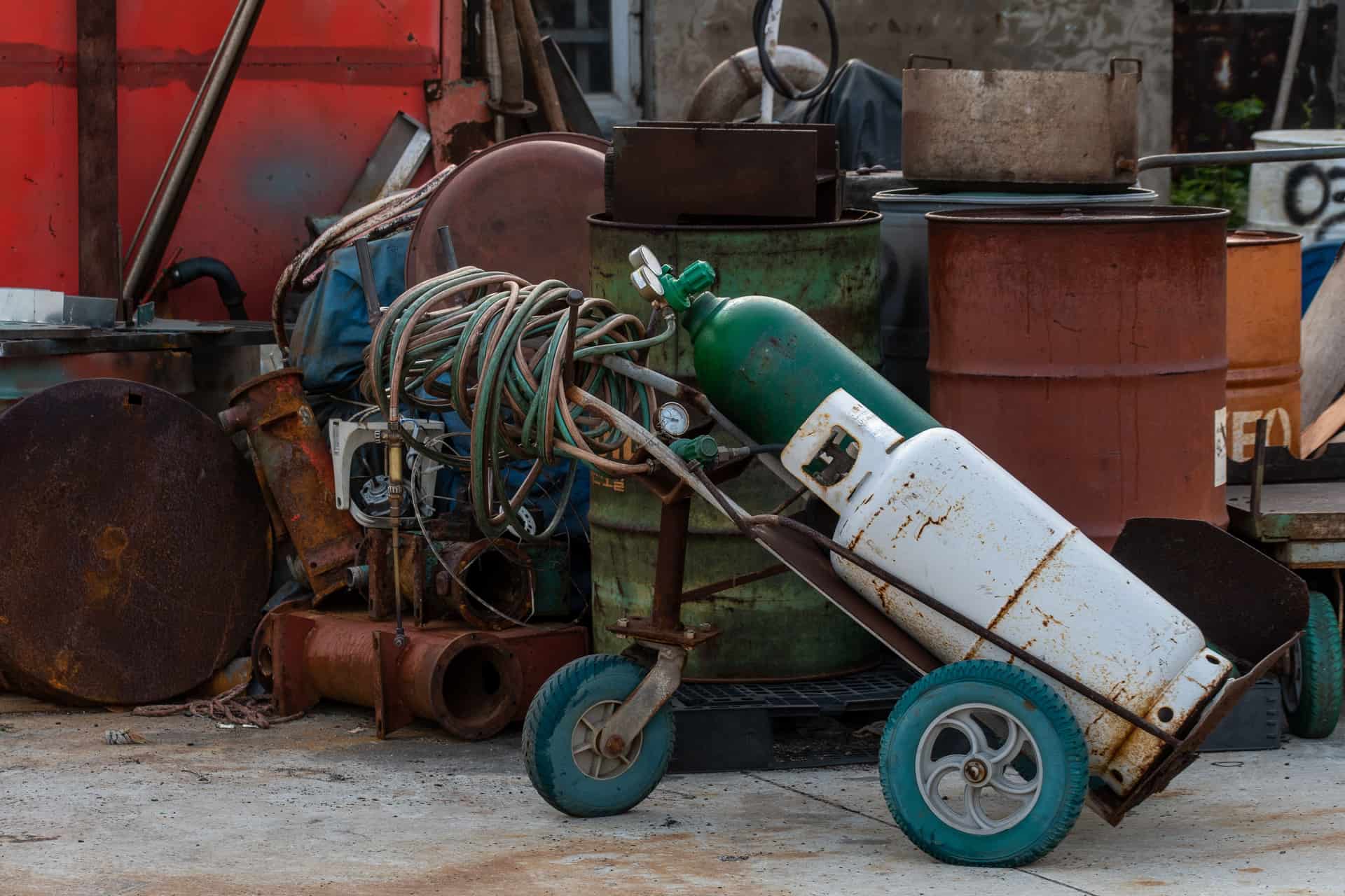
What flow rate for MIG welding?
Set 20–25 CFH (9–12 L/min) for short-circuit MIG on mild steel with a 75/25 argon-CO2 mix, indoors, with a standard nozzle. Go to 25–30 CFH (12–14 L/min) for 100% argon on aluminum, for a large-diameter nozzle, or when welding out of position. Only go above 30–35 CFH (14–17 L/min) in a draft, and fix the draft instead if you can. More gas is not more protection: above roughly 35 CFH the flow turns turbulent at the nozzle and pulls surrounding air into the shielding envelope, so raising the flow to cure porosity usually makes it worse.
Flow rate is the setting people change when a weld goes porous, and it is almost never the cause. Getting it right once and then leaving it alone removes a whole category of wasted troubleshooting.
Flow rate chart
| Situation | CFH | L/min | Note |
|---|---|---|---|
| Mild steel, 75/25 argon-CO2, indoors, standard nozzle | 20–25 | 9–12 | The default. Covers the large majority of home-shop MIG |
| Mild steel, 100% CO2 | 20–25 | 9–12 | Same range; CO2 is denser so it holds position slightly better |
| Thin sheet, short tacks | 15–20 | 7–9 | Lower end is fine; the arc time is short and the puddle small |
| Stainless, argon-rich mix | 20–25 | 9–12 | Flow is not the stainless variable — gas composition is |
| Aluminum, 100% argon, spool gun | 25–30 | 12–14 | Argon is lighter than a 75/25 mix and the puddle is wider |
| Out of position (vertical, overhead) | 25–30 | 12–14 | Gas falls away from an overhead joint rather than pooling in it |
| Large-diameter or gas-lens nozzle | 25–30 | 12–14 | A bigger orifice needs more volume for the same coverage |
| Unavoidable draft | 30–35 | 14–17 | Last resort. A screen or a closed door beats any flow setting |
| Above 35 CFH | — | — | Turbulent. Pulls air into the shield and causes the porosity you are chasing |
Why more gas makes it worse
Shielding gas works by displacing air from the area around the arc. Oxygen and nitrogen dissolve into molten steel and come back out as bubbles as it solidifies — those bubbles are the pinholes and worm tracks you see in a porous bead.
That makes it tempting to think of gas like water from a hose: more is more coverage. It is not. Gas leaves the nozzle as a column, and a column of gas only stays coherent up to a certain velocity. Push past it and the flow becomes turbulent, and turbulence at the nozzle edge does exactly the thing you are trying to prevent — it mixes the surrounding air into the shielding envelope and carries it to the puddle.
So the flow-rate curve has a plateau and then falls off. Too little gas is porous; the plateau is clean; too much is porous again, for the opposite reason. Somebody who responds to porosity by turning the regulator up will cross the plateau and conclude that gas does not help.
The things that actually cause porosity
Before you touch the flow setting, work through these. They cause porosity far more often than the number on the flow tube does.
A draft. A fan, an open garage door, a through-breeze. It takes surprisingly little air movement to strip shielding gas off a puddle, and no flow setting beats blocking the draft. This is the single most common cause in a home garage, and it is why welding outdoors with gas MIG is a poor idea — the honest answer outdoors is self-shielded flux-core, which do you need gas for MIG welding covers.
A spatter-clogged nozzle. Spatter builds up inside the nozzle and around the contact tip and disrupts the gas column before it ever reaches the work. A nozzle you cannot see cleanly through is a shielding problem, not a cosmetic one.
Dirty material. Mill scale, paint, galvanizing, oil, cutting fluid and rust all produce gas as they burn. Shielding cannot protect a puddle from contamination that is already inside it.
A leak. A kinked or perished hose, a loose fitting or a failed O-ring means the flow tube reads one thing and the gun delivers another. Soapy water on every joint is the five-minute test.
Too much stickout. Holding the gun far from the work puts the puddle outside the shielding envelope entirely. The flow is fine; the puddle is not in it.
The wrong gas. 100% CO2 on aluminum, or a 75/25 mix on aluminum, is not a flow problem. What gas for MIG welding sorts that out by metal, and 75/25 argon-CO2 vs 100% argon covers the mix question properly.
The surge nobody warns you about
When you release the trigger, gas pressure builds between the solenoid and the nozzle. On the next trigger pull, that pressure dumps as a surge well above your set flow — turbulent, air-entraining, and arriving at exactly the moment the puddle is starting. That is why so much porosity appears at the start of a bead. A shorter gun hose, a lower set flow and a pre-flow setting if your machine has one all reduce it. Striking the arc a half-inch before your actual start point and welding back over it is the technique fix.
How long a cylinder lasts at each flow rate
Flow rate is the biggest lever you have over gas cost, and the arithmetic is simple division: cylinder capacity in cubic feet, divided by flow in cubic feet per hour, gives hours of arc time.
| Cylinder | At 20 CFH | At 25 CFH | At 30 CFH | At 35 CFH |
|---|---|---|---|---|
| 40 cu ft | 2.0 h | 1.6 h | 1.3 h | 1.1 h |
| 80 cu ft | 4.0 h | 3.2 h | 2.7 h | 2.3 h |
| 125 cu ft | 6.3 h | 5.0 h | 4.2 h | 3.6 h |
| 250 cu ft | 12.5 h | 10.0 h | 8.3 h | 7.1 h |
Two things to take from that table. First, the difference between 20 and 35 CFH is close to half your gas bill, which is the practical argument for not leaving the flow high "just in case". Second, these are arc hours. Most home welding is a few minutes of arc in an afternoon of fitting, grinding and swearing, so a 125 cubic foot bottle is a long time — welding gas cylinder sizes covers which size to start with and whether to lease, exchange or own.
Setting it, and checking it
Set the flow with gas flowing, not with the gun idle. A flowmeter reads meaningfully only while gas is moving, so pull the trigger with the wire feed disabled if your machine allows it, or run a short burst on scrap and adjust between bursts.
Then leave it. A single flow setting covers nearly every job a home shop does, and the regulator is not the knob to reach for when a bead looks wrong — the MIG settings chart by thickness is where the voltage and wire speed answers live, and MIG welding sheet metal covers the thin-gauge case where everything is more sensitive.
What we would buy
Arc & Bead is an Amazon Associate. If you buy through a link on this page we may earn a commission, at no extra cost to you. We have not physically tested the machines on this page and we say so on How We Pick.
1. The tool that sets the number
Victor GRF400-580 argon/CO2 flowmeter regulator
A true flow tube reading directly in cubic feet per hour, with a 5–50 SCFH argon range and the CGA-580 inlet a US gas supplier will hand you.
Victor publishes argon, argon/CO2 mix and helium service; a CGA-580 inlet; a flowmeter regulator with a full brass body and a Lexan flow tube; flow ranges of 5 to 50 SCFH argon, 5 to 40 SCFH carbon dioxide and 20 to 150 SCFH helium; and a 3,000 psi maximum inlet.
The distinction that matters on this page is a flow tube versus a flow gauge. A gauge reads pressure at a fixed orifice and converts it to an implied flow, which is accurate only when everything downstream matches the assumption the orifice was calibrated for. A tube has a ball floating in a tapered column and shows you the actual gas passing through it. At the low flows MIG uses, that difference is large enough to matter.
It also reads directly in cubic feet per hour, which is the unit every settings chart on this site and in every manufacturer procedure sheet uses. A regulator reading in psi requires you to translate, and translation is where people end up at 50 CFH by accident.
Three honest costs. It is the wrong fitting for 100% CO2 bottles, which use CGA-320. It costs several times a generic two-gauge regulator, and a generic one will get a beginner welding. And a flow tube has to hang vertically to read correctly, which constrains where it can sit.
What works
- CGA-580 inlet is the fitting on the argon and argon/CO2 bottles a US gas supplier will hand you
- A true flow tube rather than a flow gauge, so what you read at low flow is what you are getting
- Reads directly in cubic feet per hour, which is the number the settings charts use
- Full brass body and a precision needle valve — this is a shop regulator, not a starter one
What does not
- Wrong fitting for 100% CO2 bottles, which use CGA-320 — check before you buy
- Costs several times a generic two-gauge regulator, and a generic one will get a beginner welding
- A flow tube has to hang vertically to read correctly, which constrains where it can sit on the bottle
2. What keeps the bottle upright
Klutch 2-tier welding cart with cabinet
An integral cylinder rack for a bottle up to 7 in diameter, which is the single most important safety change once you own gas.
Klutch publishes capacity for a welder or plasma cutter plus a gas cylinder, cables and consumables; an integral cylinder rack for one bottle up to 7 inches in diameter; a 31.5 x 16.1 inch footprint; a 100 lb capacity; a locking cabinet 19-1/2 x 14 x 12 inches; and two 2 inch front swivel casters with two 6 inch rear wheels.
A cart belongs on a flow-rate page for a boring and important reason: a cylinder that is not secured is the one piece of equipment in a home shop that can do structural damage. A knocked-over bottle with the regulator still fitted can shear the valve, and a 2,000-plus psi cylinder with a sheared valve is a projectile.
The practical half is that the cart is what makes a gas setup usable at all. A bottle that lives on the floor in a corner means dragging a hose across the shop, and a dragged hose is a hose that gets stood on, kinked and eventually leaks — which shows up as a flow reading that does not match what is reaching the gun.
Three costs. The 100 lb capacity is mostly used up by a 53 lb machine plus a bottle, so it is not the cart for a 240 V transformer welder. Assembly is fiddly. And it adds footprint to a shop that probably has none.
What works
- A secured cylinder is the single most important safety change in a home shop once you own gas
- Gets the machine and bottle moving together, which is what actually makes a gas setup usable in a garage
- The locking cabinet takes the consumables that otherwise live in four places
- Four sets of cable wraps, so the leads are not a trip hazard between jobs
What does not
- 100 lb capacity. A 53 lb machine plus a bottle is most of it, so this is not the cart for a 240 V transformer welder
- Assembly is fiddly and the hardware is not generous
- Adds footprint to a shop that probably has none to spare
Questions people actually ask
What flow rate should I use for MIG welding?
Start at 20 to 25 CFH, which is 9 to 12 litres per minute, for short-circuit MIG on mild steel with a 75/25 argon-CO2 mix indoors with a standard nozzle. That range covers the large majority of home-shop MIG welding.
Go to 25 to 30 CFH for 100% argon on aluminum, for a large-diameter nozzle, or when welding out of position. Only exceed 30 to 35 CFH if there is a draft you cannot eliminate.
Can you use too much shielding gas?
Yes, and it causes the same porosity that too little gas does. Gas leaves the nozzle as a coherent column only up to a certain velocity; push past it and the flow turns turbulent, and turbulence at the nozzle edge mixes surrounding air into the shielding envelope.
That is why turning the regulator up in response to a porous weld usually makes it worse. Above roughly 35 CFH you are adding air, not removing it.
How do I convert CFH to litres per minute?
Multiply CFH by 0.472. One cubic foot is 28.3168 litres, so one cubic foot per hour is 28.3168 divided by 60, which is 0.472 litres per minute.
In practice: 20 CFH is about 9.4 L/min, 25 CFH is about 11.8 L/min, and 30 CFH is about 14.2 L/min. US regulators are usually marked in CFH and European ones in L/min.
Why is my MIG weld porous if the flow rate is correct?
Work through the causes that beat flow rate. A draft is the most common in a home garage - it takes very little air movement to strip shielding off a puddle. Then a spatter-clogged nozzle, dirty material such as mill scale, paint, galvanizing or oil, a leaking or kinked hose, and too much stickout putting the puddle outside the gas envelope.
Porosity at the start of a bead specifically is usually the gas surge: pressure builds between the solenoid and the nozzle while the trigger is released and dumps turbulently on the next pull.
How long does a bottle of shielding gas last?
Divide the cylinder's capacity in cubic feet by your flow rate in cubic feet per hour to get hours of arc time. An 80 cubic foot bottle at 20 CFH is 4 hours; at 35 CFH it is about 2.3 hours.
Those are arc hours, not shop hours. Most home welding is a few minutes of actual arc time in an afternoon of fitting and grinding, so a 125 cubic foot bottle lasts a long time in calendar terms.
Is a flowmeter better than a flow gauge?
For the low flows MIG uses, yes. A flow gauge reads pressure at a fixed orifice and converts that to an implied flow, which is only accurate when everything downstream matches what the orifice was calibrated for.
A flowmeter has a ball floating in a tapered tube and shows the gas actually passing through. The Victor GRF400-580 is a flowmeter regulator reading directly in cubic feet per hour, which is the unit every procedure chart uses. A flow tube does have to hang vertically to read correctly.
Should I set the flow rate with the gun running?
Yes. A flowmeter only reads meaningfully while gas is moving, so setting it on a static system tells you very little.
Pull the trigger with the wire feed disabled if your machine allows that, or run short bursts on scrap and adjust between them. Setting it once correctly is enough - a single flow setting covers nearly every job a home shop does.
Sources
- Victor — GRF400-580 flowmeter regulator published specifications: argon, argon/CO2 and helium service, CGA-580 inlet, 5–50 SCFH argon and 5–40 SCFH carbon dioxide, 3,000 psi maximum inlet, brass body with Lexan flow tube
- Klutch — 2-tier welding cart published specifications: integral cylinder rack for one bottle up to 7 in diameter, 31.5 x 16.1 in footprint, 100 lb capacity, locking cabinet
- Unit conversion: 1 cubic foot = 28.3168 litres, therefore 1 CFH = 0.472 L/min. Cylinder-duration figures on this page are capacity divided by flow rate
Read next
- What gas do you need for MIG welding?
Which shielding gas for which metal, and the one combination that cannot work.
- Welding gas cylinder sizes
What each common cylinder holds, how long it lasts at real flow rates, and lease versus buy.
- 75/25 argon/CO2 vs 100% argon: which do you need?
Not two grades of one thing — two gases for two metals. What happens when you swap them.
- MIG welding settings chart
Starting settings by thickness, plus symptom-by-symptom diagnosis for a bad MIG bead.
- Do you need gas for MIG welding?
When shielding gas is genuinely required and when flux-cored wire is the better answer.
- Gas and power: the two things that decide what you can actually run
A machine you cannot plug in is a machine you do not own yet. This is the hub for the two questions that quietly decide every purchase on this site.
Back to Gas & Power, or start over at Find Your Level.
Ryder M.
Ryder M. is the hands-on owner behind Magoo Media Group. He writes Arc & Bead's buying guides and picks every machine on the site. What every recommendation is based on — and what it is not based on — is set out on How We Pick.